Hydraulic schematics play a crucial role in various industries, serving as a blueprint for understanding and troubleshooting hydraulic systems. Whether you are an engineer, technician, or simply interested in learning about hydraulic systems, this comprehensive guide will provide you with the necessary knowledge to read hydraulic schematics effectively.
Importance of Hydraulic Schematics in Various Industries
Hydraulic systems are widely used in industries such as manufacturing, construction, agriculture, and transportation. These systems utilize fluid power to generate, control, and transmit energy, making them essential for the operation of heavy machinery and equipment. Hydraulic schematics serve as a visual representation of these systems, allowing professionals to understand their intricate workings and identify potential issues.
Purpose of the Blog Post: Providing a Comprehensive Guide
The purpose of this blog post is to equip readers with a comprehensive understanding of hydraulic schematics. By breaking down the complex symbols and components, explaining their functions, and providing step-by-step guidance on reading schematics, this guide aims to empower individuals to confidently analyze and interpret hydraulic systems.
Understanding hydraulic schematics is a valuable skill that can enhance your problem-solving abilities, improve maintenance practices, and increase operational efficiency. Whether you are involved in system design, troubleshooting, or maintenance, having a solid grasp of hydraulic schematics will undoubtedly benefit you in your professional endeavors.
In the next section, we will delve into the basics of hydraulic schematics, including their definition, purpose, and common symbols.
Understanding the Basics of Hydraulic Schematics
Hydraulic schematics are essential in various industries, as they provide a visual representation of hydraulic systems. These schematics help engineers and technicians understand how hydraulic systems work and enable them to troubleshoot and maintain these systems effectively. In this section, we will delve into the basics of hydraulic schematics, including their definition, common symbols, and different types.
Definition and Purpose of Hydraulic Schematics
Hydraulic schematics, also known as hydraulic circuit diagrams or hydraulic diagrams, are graphical representations of hydraulic systems. They use standardized symbols to depict the various components and connections within a hydraulic system. These schematics are crucial for understanding the flow of hydraulic fluid, the functioning of different components, and the overall operation of the system.
The primary purpose of hydraulic schematics is to provide a clear and concise representation of hydraulic systems. They allow engineers and technicians to analyze and interpret the system’s functionality, identify potential issues, and design or modify hydraulic systems accordingly. By understanding hydraulic schematics, professionals can effectively troubleshoot, repair, and maintain hydraulic systems.
Common Symbols and Their Meanings
Hydraulic schematics utilize a set of standardized symbols to represent different hydraulic components and connections. These symbols are universally recognized and enable easy interpretation of the schematics. Here are some common symbols used in hydraulic schematics:
| Symbol | Component | Meaning |
|---|---|---|
 | Hydraulic Pump | Represents a pump that generates hydraulic pressure to move fluid through the system. |
 | Valve | Represents a device that controls the flow of hydraulic fluid. Different valve symbols indicate various valve types, such as directional control valves, pressure control valves, and flow control valves. |
 | Cylinder | Represents a linear actuator that converts hydraulic pressure into linear motion. |
 | Hydraulic Motor | Represents a motor that converts hydraulic pressure into rotational motion. |
 | Filter | Represents a device that removes contaminants from the hydraulic fluid. |
 | Reservoir | Represents a container that stores hydraulic fluid. |
These symbols, along with others, form the building blocks of hydraulic schematics and enable professionals to understand the components and connections within a hydraulic system.
Different Types of Hydraulic Schematics
There are several types of hydraulic schematics, each serving a specific purpose. The most common types include:
Block Diagrams: Block diagrams provide a simplified representation of a hydraulic system, focusing on the major components and their interconnections. They are useful for understanding the overall system layout and flow paths.
Circuit Diagrams: Circuit diagrams provide a more detailed representation of a hydraulic system, including all the components, connections, and flow paths. They are commonly used for troubleshooting and designing hydraulic systems.
Pictorial Diagrams: Pictorial diagrams use realistic images of hydraulic components instead of standardized symbols. They are helpful for visualizing the physical appearance and arrangement of components within a hydraulic system.
Cutaway Diagrams: Cutaway diagrams depict the internal structure of hydraulic components, such as pumps, valves, and cylinders. They provide a detailed view of the component’s construction and help in understanding its operation.
Understanding the different types of hydraulic schematics allows professionals to choose the most appropriate type for their specific needs and effectively analyze hydraulic systems.
In conclusion, understanding the basics of hydraulic schematics is crucial for professionals working with hydraulic systems. By comprehending the definition, purpose, common symbols, and different types of hydraulic schematics, engineers and technicians can gain valuable insights into hydraulic systems’ functionality and troubleshoot them effectively. In the next section, we will explore the various components of hydraulic schematics in detail.
Components of Hydraulic Schematics
Hydraulic schematics play a crucial role in various industries, helping engineers and technicians understand the complex systems that power machinery and equipment. To effectively read and interpret hydraulic schematics, it is important to have a solid understanding of the different components involved. In this section, we will explore the key components of hydraulic schematics.
Hydraulic pumps and motors
Hydraulic pumps and motors are the heart of any hydraulic system. Pumps are responsible for generating the necessary hydraulic pressure to drive the fluid through the system, while motors convert the hydraulic energy back into mechanical energy to power the machinery. These components come in various types, such as gear pumps, vane pumps, and piston pumps, each with its own advantages and applications.
Valves and their functions
Valves are essential for controlling the flow and direction of hydraulic fluid within the system. They regulate the pressure, flow rate, and direction of the fluid to ensure smooth operation and prevent damage to the equipment. Common types of valves used in hydraulic systems include directional control valves, pressure control valves, flow control valves, and check valves. Understanding the functions and symbols associated with these valves is crucial for accurately interpreting hydraulic schematics.
Actuators and cylinders
Actuators are devices that convert hydraulic energy into mechanical motion. They are responsible for moving or controlling various parts of the machinery. Cylinders, which are a type of actuator, are commonly used to generate linear motion. They consist of a piston and a cylinder barrel, with hydraulic pressure pushing the piston to move in a specific direction. Other types of actuators include hydraulic motors, which convert hydraulic energy into rotational motion, and hydraulic rams, which provide linear motion with a larger force.
Filters and reservoirs
Filters and reservoirs are vital components of hydraulic systems that help maintain the cleanliness and proper functioning of the hydraulic fluid. Filters remove contaminants and particles from the fluid, preventing damage to the components and ensuring smooth operation. Reservoirs, also known as hydraulic tanks, store the hydraulic fluid and provide a steady supply for the system. They also help dissipate heat and allow air bubbles to escape.
Understanding the role and function of these components is essential for accurately interpreting hydraulic schematics. By familiarizing yourself with hydraulic pumps and motors, valves, actuators and cylinders, as well as filters and reservoirs, you will be better equipped to read and analyze hydraulic schematics effectively.
In the next section, we will delve into the step-by-step process of reading hydraulic schematics, providing you with the necessary tools to navigate and understand these diagrams with confidence.
Reading Hydraulic Schematics Step-by-Step
Reading hydraulic schematics can be intimidating for beginners, but with a step-by-step approach, it becomes much easier to understand and interpret these complex diagrams. In this section, we will break down the process of reading hydraulic schematics into four simple steps.
Identifying the power source and direction of flow
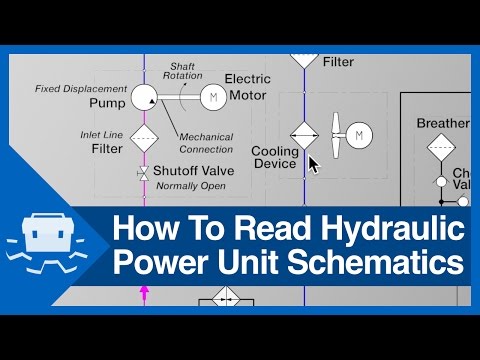
The first step in reading hydraulic schematics is to identify the power source and the direction of flow. This can usually be found at the top or bottom of the schematic. The power source is typically represented by a pump symbol, while the direction of flow is indicated by arrows.
Tip: Look for arrows that point towards or away from the pump symbol to determine the direction of flow. The arrows represent the movement of hydraulic fluid through the system.
Understanding the control valves and their positions
The next step is to understand the control valves and their positions in the hydraulic system. Control valves are crucial in regulating the flow and pressure of hydraulic fluid. They are represented by various symbols, such as squares, circles, or diamonds, depending on their functions.
To interpret the control valves, pay attention to their positions. Open valves are depicted as lines crossing the flow path, while closed valves are shown as lines perpendicular to the flow path. By understanding the positions of the control valves, you can determine which components are activated or deactivated in the system.
Tip: Take note of the symbols and their corresponding functions. Familiarize yourself with common control valve symbols to quickly identify their positions and understand their impact on the hydraulic system.
Analyzing the flow paths and connections
Once you have identified the power source, direction of flow, and control valves, it’s time to analyze the flow paths and connections in the hydraulic system. Flow paths are represented by lines that connect various components, such as pumps, valves, and actuators.
To analyze the flow paths, follow the lines and observe any branches or intersections. These indicate the flow direction and the connections between different components. Understanding the flow paths helps you visualize how hydraulic fluid moves through the system and how different components interact with each other.
Tip: Pay close attention to the flow paths and connections, as they provide valuable insights into the functionality and operation of the hydraulic system. Take your time to trace the flow paths and understand the relationships between components.
Interpreting pressure and flow rate indicators
The final step in reading hydraulic schematics is interpreting pressure and flow rate indicators. Pressure indicators are usually represented by numbers or symbols, such as arrows or triangles, while flow rate indicators are depicted by lines with dots or triangles.
To interpret pressure indicators, look for numerical values that indicate the pressure level in the system. Higher numbers represent higher pressure, while lower numbers indicate lower pressure. Flow rate indicators, on the other hand, provide information about the rate at which hydraulic fluid flows through the system.
Tip: Pay attention to the pressure and flow rate indicators to understand the performance and efficiency of the hydraulic system. By interpreting these indicators, you can identify potential issues or bottlenecks in the system and make necessary adjustments.
By following these four steps, you can effectively read and interpret hydraulic schematics. Remember to take your time, practice regularly, and refer to online resources or seek guidance from experts if needed. With patience and persistence, you can master the art of reading hydraulic schematics and gain a deeper understanding of hydraulic systems.
In the next section, we will explore some tips and tricks for mastering hydraulic schematics, including practical examples, online resources, and preventive maintenance based on schematic analysis. Stay tuned!
Note: This article is a simplified guide to reading hydraulic schematics and does not cover all possible scenarios or symbols. Always refer to the specific schematic and consult experts for accurate interpretation and analysis.
Tips and Tricks for Mastering Hydraulic Schematics
Understanding hydraulic schematics is crucial for professionals in various industries. These diagrams provide a visual representation of hydraulic systems and help in troubleshooting and maintenance. To master the art of reading hydraulic schematics, here are some tips and tricks to follow:
Practice with real-life examples
One of the best ways to improve your understanding of hydraulic schematics is to practice with real-life examples. Find schematics related to the industry you work in and study them closely. Identify the different components, symbols, and connections. By regularly practicing with actual schematics, you will become more familiar with the layout and interpretation of these diagrams.
Utilize online resources and tutorials
The internet is a treasure trove of resources for learning about hydraulic schematics. There are numerous websites, forums, and video tutorials available that provide detailed explanations and examples. Take advantage of these resources to enhance your knowledge and skills. Online platforms often offer interactive exercises and quizzes that can help reinforce your understanding of hydraulic schematics.
Seek guidance from experts in the field
If you are struggling to grasp certain concepts or find yourself stuck on a particular schematic, don’t hesitate to seek guidance from experts in the field. Reach out to experienced professionals or join industry-specific communities where you can ask questions and seek advice. Engaging in discussions with experts will not only help clarify your doubts but also provide valuable insights and practical tips.
Take note of common mistakes and how to avoid them
When learning any new skill, it’s important to be aware of common mistakes and how to avoid them. Reading hydraulic schematics is no different. Pay attention to common errors that beginners tend to make, such as misinterpreting symbols or misreading flow paths. By understanding these pitfalls, you can actively avoid them and improve your accuracy in reading hydraulic schematics.
Remember, mastering hydraulic schematics takes time and practice. Be patient with yourself and keep challenging yourself with more complex schematics as you progress. The more you immerse yourself in studying and analyzing hydraulic schematics, the better you will become at deciphering these diagrams.
In conclusion, understanding hydraulic schematics is essential for professionals working with hydraulic systems. By following these tips and tricks, you can enhance your skills in reading hydraulic schematics and become more proficient in troubleshooting and maintaining hydraulic systems. So, start practicing, utilize online resources, seek guidance, and learn from common mistakes to become a master of hydraulic schematics.
Troubleshooting Hydraulic Systems using Schematics
Hydraulic systems are widely used in various industries for their efficiency and power. However, like any complex system, they can encounter issues that require troubleshooting. Understanding hydraulic schematics can greatly aid in identifying and resolving these problems. In this section, we will explore how to troubleshoot hydraulic systems using schematics.
Identifying potential issues through schematics
One of the first steps in troubleshooting hydraulic systems is to identify potential issues. Hydraulic schematics provide a visual representation of the system, allowing you to pinpoint areas that may be causing problems. By studying the schematic, you can identify components that are not functioning correctly or potential areas of leakage or blockage.
Using schematics to locate and fix problems
Once you have identified potential issues, hydraulic schematics can help you locate the exact source of the problem. By following the flow paths and connections in the schematic, you can trace the hydraulic circuit and find the component or area that requires attention. This can save valuable time and effort in finding and fixing the problem, as you can directly target the specific area instead of searching blindly.
Preventive maintenance based on schematic analysis
Hydraulic schematics not only aid in troubleshooting existing problems but also play a crucial role in preventive maintenance. By regularly analyzing the schematics, you can identify potential weak points or areas that may require maintenance in the future. This proactive approach can help prevent major breakdowns and extend the lifespan of your hydraulic system.
For example, if you notice excessive pressure drops in certain areas of the schematic, it may indicate a clogged filter or a worn-out valve. By addressing these issues before they escalate, you can prevent system failures and costly repairs.
Mastering the art of reading hydraulic schematics is essential for troubleshooting hydraulic systems effectively. By understanding the basics of hydraulic schematics, identifying potential issues, and using schematics to locate and fix problems, you can save time, effort, and money in maintaining and repairing hydraulic systems.
Remember to practice with real-life examples, utilize online resources and tutorials, and seek guidance from experts in the field to enhance your schematic reading skills. By doing so, you can become proficient in troubleshooting hydraulic systems and ensure the smooth operation of your hydraulic machinery.
In conclusion, the benefits of understanding hydraulic systems and being able to troubleshoot them using schematics are invaluable. It empowers you to take control of your hydraulic systems, minimize downtime, and maximize productivity. So, invest the time and effort to master hydraulic schematics, and you will reap the rewards in the long run.
Hydraulic schematics play a crucial role in various industries, providing a visual representation of hydraulic systems. Understanding these schematics is essential for professionals working with hydraulic systems. This comprehensive guide aims to provide a step-by-step approach to reading hydraulic schematics.
Understanding the Basics of Hydraulic Schematics
Hydraulic schematics are diagrams that illustrate the flow of hydraulic fluid within a system. They use standardized symbols to represent different components and their functions. By familiarizing yourself with these symbols, you can decipher the information conveyed in hydraulic schematics. There are different types of hydraulic schematics, including block diagrams, cutaway diagrams, and pictorial diagrams.
Components of Hydraulic Schematics
To effectively read hydraulic schematics, it is important to understand the various components involved. These components include:
Hydraulic pumps and motors: These devices generate hydraulic pressure, converting mechanical energy into hydraulic energy.
Valves and their functions: Valves control the flow of hydraulic fluid within the system. Different types of valves, such as directional control valves and pressure control valves, serve specific purposes.
Actuators and cylinders: Actuators convert hydraulic energy into mechanical energy, allowing for the movement of various machine parts. Cylinders are a common type of actuator used in hydraulic systems.
Filters and reservoirs: Filters remove contaminants from the hydraulic fluid, ensuring the system operates smoothly. Reservoirs store the hydraulic fluid and help regulate its temperature.
Reading Hydraulic Schematics Step-by-Step
To read hydraulic schematics effectively, follow these steps:
Identify the power source and direction of flow: Determine where the hydraulic fluid is coming from and the direction it travels within the system.
Understand the control valves and their positions: Analyze the symbols representing control valves and their positions to comprehend how they regulate fluid flow.
Analyze the flow paths and connections: Study the lines and arrows in the schematic to understand the flow paths and connections between different components.
Interpret pressure and flow rate indicators: Pay attention to symbols indicating pressure and flow rate to understand the system’s performance characteristics.
Tips and Tricks for Mastering Hydraulic Schematics
Mastering hydraulic schematics requires practice and continuous learning. Here are some tips to help you improve your skills:
Practice with real-life examples: Work with actual hydraulic systems and their schematics to gain hands-on experience.
Utilize online resources and tutorials: Take advantage of online resources, such as video tutorials and interactive simulations, to enhance your understanding.
Seek guidance from experts in the field: Collaborate with experienced professionals who can provide valuable insights and guidance.
Take note of common mistakes and how to avoid them: Learn from common mistakes made when reading hydraulic schematics and develop strategies to avoid them.
Troubleshooting Hydraulic Systems using Schematics
Hydraulic schematics are invaluable tools for troubleshooting hydraulic systems. By referring to the schematics, you can:
Identify potential issues: Analyze the schematic to identify potential problem areas within the system.
Locate and fix problems: Use the information in the schematic to locate the source of the issue and take appropriate corrective measures.
Perform preventive maintenance: Regularly analyze hydraulic schematics to identify areas that may require preventive maintenance, ensuring the system operates efficiently.
Mastering the skill of reading hydraulic schematics is essential for professionals working with hydraulic systems. By understanding the symbols, components, and flow paths depicted in hydraulic schematics, you can effectively troubleshoot issues, perform maintenance, and ensure optimal system performance. Remember to practice regularly, seek guidance from experts, and utilize available resources to enhance your schematic reading skills. With time and dedication, you will become proficient in deciphering hydraulic schematics and reap the benefits of a thorough understanding of hydraulic systems.
